

Best Control Transformer Manufacturer for Reliable Power Distribution
2026-11-02
Power distribution isn't glamorous until it fails—then it's the only thing anyone talks about. Control transformers are at the heart of that reliability, and not every manufacturer earns the title of best. Wenma has spent years proving itself as the best control transformer manufacturer for reliable power distribution by designing products that handle real-world demands. This post explores what to look for, what to avoid, and why Wenma keeps ending up on shortlists.
Why Transformer Core Materials Decide Long-Term Stability
The slow degradation of a transformer rarely starts in the windings. More often, it begins inside the core, where repeated magnetic cycling causes microscopic dimensional changes. In grain-oriented silicon steel, magnetostriction strains the laminations just enough to wear through the thin insulating coating over years of service. Once that coating breaks down, eddy currents find new paths, local heating rises, and the core begins to consume slightly more energy while operating at a higher temperature—a quiet feedback loop that steadily shortens insulation life elsewhere in the unit.
Material choice also determines how the core handles harmonic-rich loads. Amorphous and nanocrystalline ribbons have lower losses than conventional silicon steel, but they are brittle and more sensitive to clamping pressure. If the clamping system relaxes or was set slightly too tight during assembly, those materials can develop microcracks. Each crack acts as an air gap, altering flux distribution and creating hot spots that are difficult to detect until a routine thermal scan shows an unexpected rise. By then, the core has often already shifted from stable operation into a pattern of accelerating wear.
Corrosion resistance plays an equally quiet role. Cores exposed to moisture or mild acids—even from transformer oil breakdown—can develop surface rust on laminations. This rust is not just cosmetic; it increases contact resistance between layers and promotes further oxidation. A core material with poor corrosion resilience, or one with a damaged protective phosphate coating, will degrade faster in the same environment than a material designed for long-term chemical stability. Over a decade or two, these small material-level differences accumulate into measurable changes in no-load loss and excitation current, which are early warnings of reliability drift.
A Closer Look at Winding Techniques That Reduce Hotspots
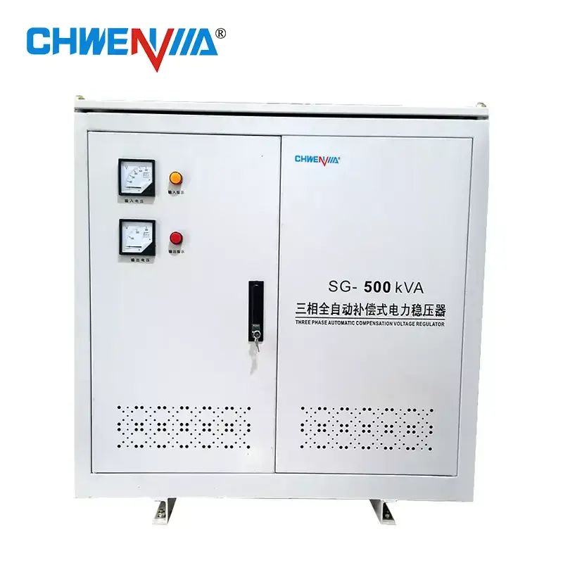
Hotspots in wound components rarely come from a single cause. They usually appear when current crowds toward one edge of a conductor or when adjacent turns don't share the load evenly. One practical fix is to interleave primary and secondary layers so that each turn sits in a slightly different magnetic field, which flattens the current distribution. Another approach is to use multiple parallel strands with a slight twist, so every strand spends some time near the core and some time near the outer surface.
Layer-to-layer spacing also matters more than it might seem. If the insulation is uneven, turns can press together and create a small pocket of higher temperature. Some builders offset each layer by half a turn width, which prevents a straight radial stack of conductors. That simple shift forces heat to spread sideways instead of building up in one column. Foil windings, when used with careful edge termination, can also reduce hot spots by giving current a wider path, but they need very flat surfaces to be effective.
Finally, tension control during winding is often the difference between a cool-running coil and one with repeated failures. Too much tension deforms the wire and thins the insulation; too little leaves gaps that lead to vibration and uneven contact. A steady, moderate pull, combined with a thin layer of thermally conductive varnish between layers, helps pull heat away from the core and into the surrounding air or potting material.
Meeting Voltage Regulation Demands in Aging Grids
As distribution feeders stretch further and carry more distributed generation, voltage swings become harder to manage with legacy equipment. Tap changers and fixed capacitor banks were designed for predictable one-way power flow, not the rapid fluctuations caused by rooftop solar or shifting load patterns. Many older substations still rely on electromechanical controls that respond slowly and require frequent maintenance, leaving operators with fewer options during peak demand or high reverse power conditions.
One practical response is to combine existing assets with smarter sensing. Line post sensors and low-cost power quality monitors can give utilities real-time visibility at points where voltage was previously estimated rather than measured. This data often reveals that the actual problem is not a lack of regulation capacity but poor coordination between devices. Adjusting voltage set points, staggering capacitor switching sequences, and adding localized reactive support can bring immediate improvement without waiting for full feeder automation.
When upgrades are necessary, compact power electronics offer a targeted alternative to wholesale infrastructure replacement. Static VAR compensators and dynamic voltage restorers can be installed at critical nodes to absorb fast voltage changes and support weak sections of the grid. The goal is not to replace aging transformers and regulators all at once, but to extend their useful life by managing the stresses they face. In many cases, this staged approach reduces both capital cost and downtime while keeping voltage within required limits.
How Protective Coatings Extend Life in Corrosive Settings
Corrosion is rarely a sudden event; it is a slow, relentless process that feeds on moisture, salt, chemical vapors, and even stray electrical currents. Protective coatings alter this dynamic by forming a physical barrier between the substrate and the corrosive environment. But high-performance systems go further—they incorporate sacrificial pigments, passivating agents, or dense cross-linked polymers that actively interrupt the electrochemical reactions driving rust and pitting. In coastal refineries, for instance, a properly selected epoxy zinc-rich primer does not simply sit on the steel; it corrodes preferentially, buying years of additional service life for the structural steel behind it.
The financial and operational impact is most visible in maintenance intervals. Uncoated carbon steel in a marine atmosphere may require replacement or heavy repair within five to seven years, while a well-engineered multi-coat system can stretch that to twenty or more. This does not just delay capital expenditure—it reduces the frequency of confined space entries, scaffolding, and abrasive blasting, all of which carry their own safety and downtime costs. Plant managers often discover that the real payback comes not from the coating itself, but from avoiding the hidden expenses of repeated surface preparation and lost production hours.
Yet coating longevity depends on more than the product data sheet. Edge retention, surface profile, ambient curing conditions, and the skill of the applicator determine whether a system performs as designed or fails prematurely. Chipped corners, pinholes, and insufficient film thickness create localized weak points where corrosion starts early and spreads beneath the intact film. A rigorous inspection program using dry film thickness gauges, holiday detectors, and adhesion tests is what separates a coating that lasts a decade from one that fails in three years. In corrosive settings, the difference between mediocre and exceptional performance is rarely the chemistry alone—it is the disciplined execution at every stage, from surface preparation to final cure.
The Overlooked Link Between Quality Control and Uptime
Many teams treat quality control as a final checkpoint, a box to tick before release, but rarely connect it to how long a system stays operational. The assumption is that if the product passes inspection, uptime will take care of itself. In practice, small deviations that slip through quality gates often don't cause immediate failure—they accumulate as friction that shortens the lifespan of components or creates sporadic errors that are hard to trace.
Consider a manufacturing line where a subtle misalignment in a part passes inspection. The line keeps running, but the part wears unevenly, leading to an unexpected breakdown weeks later. The same pattern shows up in software: a code review that glosses over a race condition may not crash the service today, but under heavy load it becomes the reason for a midnight outage. Quality control failures don't always announce themselves at the moment of release; they surface later as unplanned downtime.
The reason this link stays overlooked is that quality control is often framed as a cost or compliance activity rather than a reliability driver. When teams start logging defects alongside uptime incidents, they usually find a lagging correlation: a batch of missed checks corresponds to a rise in interruptions days or weeks down the line. Shifting quality control from a one-time gate to a continuous feedback loop can turn those early warnings into preventive action, keeping systems up without relying on heroic last-minute fixes.
Designing for Load Fluctuations Without Sacrificing Efficiency
Real-world systems rarely operate at a fixed point. Compressors, pumps, and HVAC units face demand swings that can tank efficiency if the design only targets a single sweet spot. Instead of oversizing for peak load and accepting wasteful part-load behavior, engineers can use variable-speed drives paired with smart staging logic. The key is to let the equipment modulate its output rather than cycling on and off, which causes pressure spikes and thermal losses. For example, a modular chiller plant with multiple smaller compressors can run only the number needed, each near its best efficiency point, while a central controller trims speed to match the exact load.
Part-load efficiency depends heavily on how components behave away from rated capacity. Fixed-geometry impellers and constant-speed motors lose performance quickly below 80% load, but adjustable inlet guide vanes or variable-frequency drives can flatten that curve. Thermal storage adds another layer: shift excess capacity during low-demand periods and discharge it when loads spike, avoiding the need to fire up inefficient backup equipment. Even simple measures like sequencing air handlers based on zone-level sensors rather than a single thermostat reduce unnecessary runtime and keep the system closer to its design envelope.
Testing and control algorithms matter as much as hardware. A system that reacts too slowly to load changes will overshoot and waste energy, while one that reacts too fast may hunt and wear out actuators. Model predictive control, which uses short-term load forecasts and equipment performance maps, can balance this by anticipating shifts instead of chasing them. Field data from existing installations often reveals that minor tweaks—such as widening the deadband on staging or recalibrating sensor placement—recover several percentage points of efficiency without any capital cost. The goal is not to eliminate fluctuations but to design the system so that every operating point, however transient, remains as close to optimal as possible.
FAQ
They design with high-grade silicon steel cores and precision winding techniques, allowing the transformer to maintain stable secondary voltage even when incoming line voltage swings by ±10%. Many also include electrostatic shielding between primary and secondary to filter out line noise.
Beyond standard ratings, look for manufacturers that offer custom terminal blocks, multiple primary voltage taps, specific footprint constraints, and enclosures rated for washdown or hazardous locations. Flexible lead lengths and pre-wired fuse blocks are also common requests.
Control transformers often run continuously in enclosed cabinets. A well-designed unit uses grain-oriented core steel and low-loss insulation to reduce heat buildup, plus ventilation slots or encapsulated designs to dissipate heat without derating the transformer's capacity.
Yes. A transformer with tight voltage regulation and built-in transient suppression prevents voltage sags from dropping below the holding voltage of contactors and relays, which is a frequent cause of unexplained machine stoppages.
Look for UL Listed or Recognized Component status, CE marking for EU compliance, CSA approval for Canada, and insulation systems rated to Class F or H. Manufacturers with in-house testing labs and ISO 9001 processes add another layer of confidence.
Encapsulated transformers are fully sealed with epoxy or resin, making them resistant to moisture, dust, and vibration. Open core units are easier to service but require a clean, dry enclosure. For food processing or marine applications, encapsulation is usually the safer choice.
Control transformers must handle high inrush current when energizing contactor coils or solenoids. Reliable manufacturers publish inrush VA data at 20-40% power factor, allowing you to size the transformer so secondary voltage does not dip below 85% of nominal during the first few cycles.
Yes. North American units typically use 60 Hz and standard primary taps like 480/240V, while international models may require 50 Hz, 400V or 230V primaries, and different creepage/clearance distances per IEC standards. A good manufacturer will offer dual frequency and multi-tap primaries to cover both.
Conclusion
A control transformer manufacturer earns its reputation through decisions that stay invisible until a grid strains. Core materials are chosen not for initial cost but for magnetic stability over decades—silicon steel grades that resist drift and keep losses predictable. Winding techniques receive equal scrutiny: evenly tensioned, layer-built coils avoid the concentrated heat that slowly bakes insulation. On aging networks where voltage sags and swells with load changes, these units hold regulation steady without frequent tap adjustments or field service calls. It's the quiet reliability that plant managers come to depend on.
Long-term survival in harsh environments is another hallmark. Protective coatings—epoxy or polyurethane—are tested against salt fog, ammonia, and acidic runoff, so enclosures don't rust through in coastal substations or chemical plants. But the strongest signal of a best-in-class manufacturer is not a spec sheet; it's the quality control routine. Every core, every coil, every connection gets checked at intermediate stages, not just at final assembly, because a hidden defect means downtime that no warranty fully covers. And when production lines cycle from heavy motor starts to near-idle, the transformer's design keeps efficiency flat across that range, avoiding the usual trade-off between responsiveness and waste heat. That balanced approach is what separates a reliable partner from a commodity supplier.
Contact Us
Contact Person: Mr. Jiang
Email: [email protected]
Tel/WhatsApp: +86-15057775503
Website: https://www.avrfactory.com/