

China Contactor Selection Tips for Reliable Electrical Performance
2026-08-19
Selecting the right contactor is critical for any electrical system, yet sourcing from China often raises concerns about performance consistency. A single overlooked specification—from coil voltage tolerances to contact material—can lead to premature failure or even safety hazards. That’s why we’ve gathered practical, field-tested advice to help you evaluate Chinese contactors with confidence. Whether you’re replacing an existing unit or specifying for a new build, these tips from ETEK focus on real-world reliability, not just datasheet promises. Ready to move beyond guesswork and ensure your next contactor performs as expected under load? Let’s dive in.
Derate for Real Inrush, Not Nameplate Amps
Nameplate amps look tidy on paper, but they rarely tell you what happens in the first hundred milliseconds after a motor kicks on. Depending on the load, the real inrush can spike anywhere from four to ten times the listed full-load current—sometimes higher with high-efficiency motors or stiff grid connections. If you size fuses, breakers, or even thermal relays strictly off the nameplate value, you are not protecting the circuit. You are just guessing with extra steps.
A better approach is to measure the actual locked-rotor current under worst-case conditions: cold windings, maximum supply voltage, and the heaviest mechanical load the shaft will see. Use a current probe with a fast sampling rate and capture at least twenty line cycles. Then derate your protective devices and conductors against that measured inrush—not the nameplate number. For example, if the real inrush hits 38 amps on a motor tagged at 12 amps, your time-delay fuse or breaker curve must allow that 38 amps to pass long enough for normal starting without nuisance tripping, while still clearing a genuine fault.
One trap is thinking soft starters or VFDs remove the need for this. They limit inrush, but they do not eliminate it, and their own bypass contactors can still see a spike if the drive drops out under load. Measure the whole starting envelope, not just the steady-state ramp. Derating for real inrush means paying attention to the ugly, dynamic part of the curve that the nameplate conveniently leaves out.
Check Coil Pickup and Dropout Voltage Against Your Worst-Case Supply
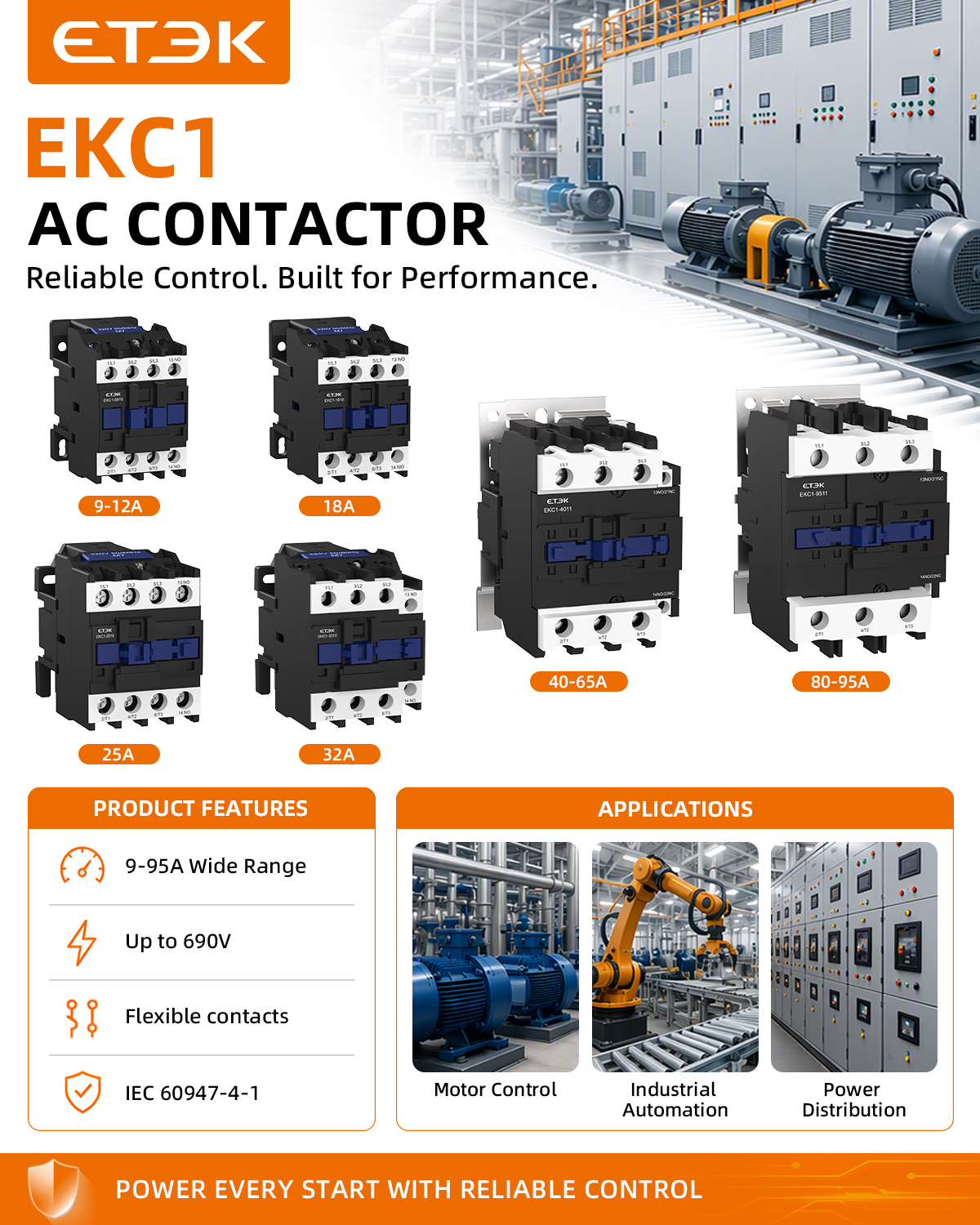
A relay coil doesn't draw a fixed current like a resistor in a textbook. As the winding heats up, its resistance climbs, and the current at a given voltage drops. That means the pickup voltage you measured on a cold bench can be misleadingly low. When your supply is at its minimum tolerance and the harness has a few hundred millivolts of drop across connectors and traces, the coil may only see 80% of nominal. If the armature chatters or fails to seat fully, contacts weld or arc. So check the actual coil terminal voltage under worst-case low-line conditions, not the power supply's output terminal.
The dropout side is just as easy to overlook. A relay that picks up cleanly at low voltage may refuse to release when the supply drifts to its upper limit. High coil voltage keeps the magnetic circuit saturated, and if the residual flux or a slightly sticky armature holds on, you get a contact that never opens. Some designs also have a noticeable hysteresis gap between pickup and dropout. Make sure the minimum dropout voltage under your highest supply condition sits comfortably below the lowest control signal that should de-energize the coil. Otherwise a brownout recovery can leave outputs stuck in the wrong state.
A practical check is to sweep the coil voltage with an adjustable bench supply while the relay is at operating temperature. Record the exact voltage where the contacts first close, then lower the voltage until they open. Do this with the actual wiring or a representative resistance in series. Compare those numbers against the manufacturer's worst-case limits, not just the typical datasheet curve. If your measured pickup is above the supply's guaranteed minimum, add a coil driver with more headroom or choose a relay with a lower coil resistance. For dropout, verify that the release voltage is well above any leakage current path that could keep the coil partially energized.
Look at Contact Material and Wiping Action, Not Just Silver Alloy Claims
Many relay and switch datasheets proudly list silver alloy contacts as if that phrase alone guarantees long life. Yet the specific alloy matters far more than the generic label. Silver cadmium oxide, silver nickel, and silver tin oxide each respond differently to arcing, oxidation, and low-level signal loads. A contact that excels at breaking heavy current may develop troublesome surface films under dry circuit conditions. Without knowing the exact composition and the contact force behind it, the claim of a silver alloy surface tells you surprisingly little about how the device will perform in the field.
Wiping action is the second half of the story, and it is often left out of promotional material entirely. When contacts close, a slight sliding motion can scrape through oxides and particulate contamination, exposing fresh metal and creating a cleaner electrical interface. This mechanical self-cleaning effect is designed into some switches and relays through specific blade geometries or actuation angles. If the contact simply slams together without any lateral movement, even a premium alloy will eventually suffer from carbon buildup or sulfidation. The wipe is not an accessory; it is part of the contact system.
So when you compare components, look past the boldface alloy claims. Ask what the actual alloy is, how the contact surfaces are shaped, what closing force is applied, and whether the mechanism produces a wiping motion during engagement. These details are far better predictors of contact resistance stability and service life than the vague promise of silver. A well-designed silver tin oxide contact with a deliberate wiping action will outperform a generic silver cadmium oxide contact that closes dead-on, every time.
Ask for Thermal Test Data Inside Your Actual Enclosure
Manufacturer datasheets often list thermal resistance values measured on a standardized test board with generous copper area and forced airflow. Those numbers rarely survive contact with a compact product housing, where nearby components radiate heat and venting may be limited. Instead of trusting junction-to-ambient figures blindly, request measurement results collected with the component mounted inside your actual enclosure, running your expected workload. This reveals hot spots, PCB temperature gradients, and whether the case itself becomes too warm to touch.
When you reach out to suppliers or internal thermal engineers, be specific. Ask for a full thermal profile at worst-case ambient temperature, with thermocouple placement on the die, exposed pad, board layers, and enclosure walls. Request data logged over at least an hour after reaching steady state, not a quick snapshot. If a fan or heatsink is part of the design, insist on testing with the same airflow path and mechanical fit as production units. The resulting graphs and infrared images give you realistic derating guidance and help you avoid overengineering or shipping a device that throttles after ten minutes.
Verify Chinese GB/T Certifications with Batch-Level Test Reports
A GB/T certificate on a supplier's website proves only that a sample once passed the relevant Chinese national standard. It says little about the goods sitting in a warehouse today. Batch-level test reports close that gap because they are tied to a specific production lot, batch number, and quantity. You can match the documentation directly to what you are buying instead of relying on a one-time type approval.
When you receive a batch report, do not just file it away. Contact the issuing laboratory directly and confirm the report number, test dates, and key values. Check that the product description, model number, and batch identifier match your purchase order exactly. Also verify that the cited standard—such as GB/T 2626 for respirators or GB/T 32610 for protective masks—actually applies to your product category. A mismatch between the standard's scope and the item is a common red flag.
Some suppliers send an old type-test report and call it a batch report. Look for a specific production date or batch code, and confirm that samples were drawn from the batch itself rather than from a prototype. If the laboratory cannot verify the document, or if the supplier hesitates to provide direct contact details, treat the certification as unconfirmed.
Judge Suppliers by Field Return Rates, Not Catalog Specs
Many procurement teams get distracted by glossy datasheets and spec sheets that promise flawless performance. But those numbers are produced in controlled conditions, not on your production line. A component may look perfect on paper and still fall apart after a few weeks in the field. That's why the return rate from actual customers or service technicians tells you far more about real-world durability.
Field return data reflects how a part behaves under vibration, temperature swings, moisture, and rough handling—conditions no catalog can replicate. One supplier might list identical tolerances to another, yet show three times the defect-related returns once installed. Tracking that metric over several quarters separates dependable vendors from those who simply write better brochures.
Make field return rates a compulsory part of your supplier scorecard. Ask for data by batch and by product family, and compare it against your own warranty claims. A slightly higher unit price is often justified by a lower return rate, because every failed part carries costs beyond the replacement: lost labor, downtime, and customer trust.
FAQ
Check the motor's full-load current and then oversize by 20-50% to handle inrush and grid voltage dips. Local contactors often have optimistic AC-3 ratings, so confirm the actual test conditions and don't rely solely on the nameplate.
The contact material and arc quenching design are frequent weak points. Silver tin oxide replacements for silver cadmium oxide can develop high contact resistance if not formulated well. Ask the supplier about the contact alloy and check whether the arc chutes are ceramic rather than low-grade plastic.
Grid fluctuations in China can be significant. A 220V AC coil may chatter with voltage sags. Select a coil with a wider tolerance band, such as 0.85 to 1.1 of nominal, or use a DC coil with an integrated rectifier for stable holding even during brownouts.
No, CCC only covers basic safety requirements. Ask for additional type-test data like IEC 60947-4-1 endurance results or third-party reports on mechanical and electrical life. Brands that also carry UL or TUV marks often have tighter production controls and better batch consistency.
Contactors are usually rated at 40°C ambient. In southern China, enclosure temperatures often exceed 55°C. Derate the thermal current by roughly 1% for every degree above 40°C, and leave more space around the contactor if it is near a VFD. Forced ventilation may be necessary.
Stick to authorized distributors or verified OEM channels. Avoid bargain listings on open marketplaces for critical applications. Compare the weight and finish with a known genuine unit—counterfeits often use thinner copper and cheaper plastics. Run a 30-minute full-load temperature rise test on samples.
AC-1 suits resistive loads, AC-3 covers normal motor starts and stops, and AC-4 handles harsh duties like plugging or inching. Many Chinese contactors carry a high AC-3 rating but struggle with frequent AC-4 cycles. Match the utilization category to the real duty; for heavy reversing, choose one frame size larger.
Conclusion
When selecting contactors in China for dependable electrical performance, it's unwise to trust nameplate amp ratings alone. Real-world inrush currents from motors, transformers, or capacitor banks often exceed nominal values, so derating based on measured or calculated inrush is essential. Equally critical is verifying coil pickup and dropout voltages against your worst-case supply fluctuations—a contactor that chatters or fails to hold under brownout conditions can cause rapid contact welding. Pay close attention to contact material and the mechanical wiping action, not just marketing claims of "silver alloy." A good wiping motion cleans oxides and reduces contact resistance over time. Also request thermal test data performed inside your actual enclosure, since heat buildup from adjacent components can push contactors past safe operating temperatures.
Beyond the hardware itself, insist on GB/T certifications backed by batch-level test reports rather than a generic certificate. This confirms consistent manufacturing quality. Finally, evaluate suppliers by their field return rates and failure histories, not just catalog specifications or glossy brochures. A low return rate over thousands of installed units tells you more about reliability than any datasheet. Combining these practical checks—derating for true inrush, validating coil voltage margins, scrutinizing contact design and thermal behavior, and demanding production-level evidence—helps you avoid unpleasant surprises in the field and build systems that last.
Contact Us
Contact Person: Andy
Email: [email protected]
Tel/WhatsApp: +86 13356133008
Website: https://www.etek-china.com/