

Mastering OEM Test Connectors: A Practical Guide to Reliable Diagnostics
2026-11-16
Nothing slows down a diagnostic workflow faster than a poor connection you didn’t see coming. OEM test connectors are often the unsung workhorses of reliable troubleshooting — until a loose pin, intermittent signal, or misdiagnosed fault forces you to question every reading. This guide strips away the guesswork, showing you how to master connector selection, maintenance, and quick sanity checks that separate sharp technicians from the pack. At REUNION, we’ve seen how a single overlooked detail can cascade into hours of wasted time, so we built this practical roadmap to keep your diagnostics accurate from the first click.
Why OEM Connectors Make or Break Your Diagnosis
A flaky voltage reading or an intermittent sensor dropout often gets blamed on a bad module, but more times than not the real culprit sits right at the connector. OEM connectors are engineered with specific pin tolerances, plating materials, and sealing geometries that generic replacements rarely match. Swap in a cheap pigtail, and you might introduce micro-fretting corrosion or a terminal drag that shaves off millivolts in a way your scope won’t immediately flag—until the car leaves you stranded on a hot restart.
The wire gauge and crimp profile inside a factory connector are matched to the vibration profile and thermal cycling of that exact spot in the harness. Aftermarket kits tend to take a one-size-fits-all approach, ignoring the fact that a MAF sensor circuit cares about nanovolt-level stability while a cooling fan just needs bulk current. When the connector loses its gas-tight grip, you chase ghost DTCs that vanish the moment you back-probe the terminal, simply because your test leads restore the tension the pin lost months ago.
Water intrusion tells a similar story. OEM connectors use cavity plugs and wire seals rated for the specific fluids they’ll encounter—engine oil, DEF, road salt slurry. Field repairs with RTV or heat shrink can trap moisture inside the shell, turning the connector body into a slow cooker for corrosion. Before condemning an ECU or tearing into a harness, put the connector under a magnifying glass. That tiny green fuzz creeping up the terminal might be the whole diagnosis.
Decoding Pinouts Without the Factory Manual
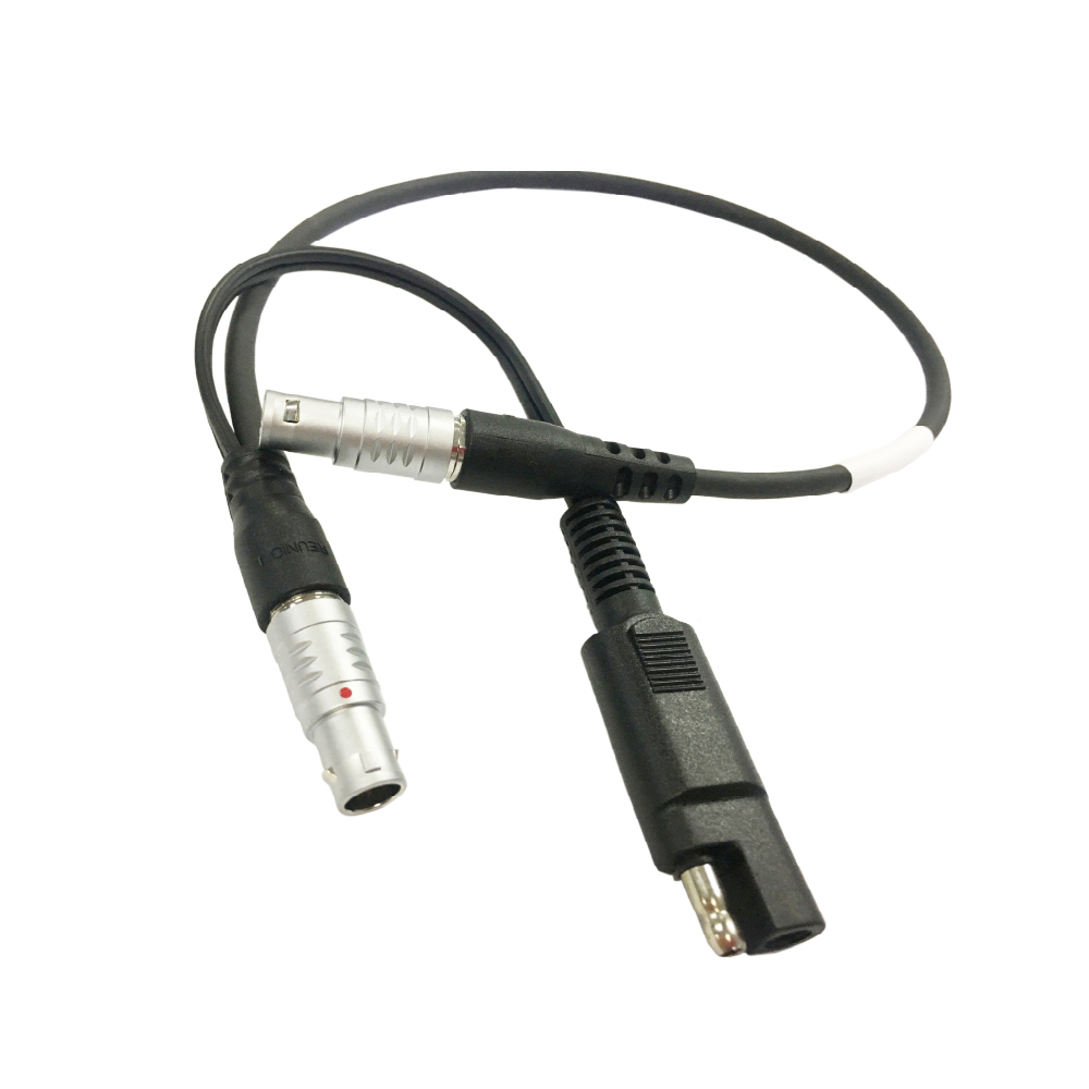
Sometimes the most direct way to understand a mystery connector is to ignore the search for a datasheet altogether and study the circuit it lives on. Grab a flashlight and a magnifier, then follow traces from each pin on the board. Where do they go? Power pins usually lead to large copper fills, the input side of a voltage regulator, or obvious decoupling capacitors. Ground pins often connect directly to a copper pour, metal shield, or the battery negative terminal. This physical reverse engineering can reveal a pin’s role faster than scrolling through bad photocopies of old service manuals.
If you can power up the device safely, a multimeter set to continuity or diode mode becomes your best ally. With the black probe firmly on a known ground point, gently probe each pin while watching the reading. A dead short to ground might be a shield connection or a ground pin—confirm by checking if it also has low resistance to the outer shell of the connector. A pin that gives a diode-like reading (typically 0.4 V to 0.7 V one way and open circuit the other) could be a signal line with internal ESD protection. Pins that show a steady voltage—like 3.3 V or 5 V—appearing as soon as the board is energized are strong candidates for power outputs, especially if they rise and fall with the device’s power button.
When you have the luxury of a working system, observing behavior during boot or data transfer can unlock the puzzle. Use a logic analyzer or even a simple LED with a current-limiting resistor to watch pins for activity. One classic trick: connect a UART adapter’s RX line through a 1 kΩ resistor to the unknown pins one at a time, set the baud rate to a common value (115200 is a good start), and see if you capture readable boot messages. If a pin toggles in bursts when you press keys or move a connected accessory, you’ve likely found a data line. Mapping these behaviors to the physical board layout often tells you more than any original documentation would.
Signal Integrity Pitfalls Most Techs Overlook
The fixation on clock frequencies and eye diagrams often buries a quieter killer: the return path. Every signal needs a completed circuit, but too many designs treat the ground plane as a magical sink that swallows noise without consequence. When high-speed edges find a split plane, a gap in the reference, or a decoupling capacitor placed on the far side of a breakout region, the return current detours disastrously. It sprays across the board, turning passive copper into resonant cavities and coupling into quiet traces. The symptom might look like intermittent data corruption that disappears when you place a finger near the PCB, but the root cause is a broken image plane that the layout team inherited from a rushed stackup decision.
Another oversight lives inside the via field. Technicians regularly swap via sizes or adjust anti-pad diameters without recalculating the impedance impact, assuming that a few mils don’t matter. In differential pairs running above 5 Gbps, the barrel inductance and the capacitive loading from oversized pads create reflection points that no amount of pre-emphasis can fully clean. The real trap is the ground via arrangement. Asymmetric stitching around a signal transition, or stitching that falls outside the return current’s immediate vicinity, injects common-mode noise that gets rectified downstream by sensitive amplifiers. This shows up as an eye diagram that gradually closes during thermal cycling because the stack relaxes and the return path discontinuity shifts with temperature.
Crosstalk misdiagnosis rounds out the common blind spots. The instinct is to look at adjacent trace spacing on the same layer, but the overlooked aggressor is often the broadside coupling between layers in thin, modern prepregs. A 2-mil separation between L3 and L4 can turn an innocent 3.3V GPIO toggling at a leisurely rate into a packet-destroying noise source for a 25 Gbps SerDes running directly above or below it. Simulation rarely catches this because pre-layout models default to worst-case coupling from immediate neighbors, and post-layout extraction misses it when the mesh is too coarse. The result is a system that passes compliance at room temperature but fails after a firmware update changes the switching pattern of an unrelated power rail.
The Back-Probing Debate: Safe Methods That Actually Work
Poking around the back of a running appliance sends a shiver through most experienced techs, and for good reason. One slip and you’ve got a fried board, a tripped breaker, or worse. Yet there’s a quiet cohort of troubleshooting veterans who lean on back-probing daily—not because they’re reckless, but because they’ve mastered a handful of techniques that sidestep the drama. The real debate isn’t about whether it’s inherently dangerous; it’s about whether you’re using tools and habits that respect the tight spaces and live circuits you’re invading.
The trick starts with your probe. Ditch the standard-sharp tips for a set of extra-fine, spring-loaded back probes with a protective sheath that only exposes the last millimeter of metal. This alone prevents accidental contact with adjacent terminals. Then, feed the probe alongside the wire, not against it, letting the silicone insulation of the connector guide you. A tiny dab of dielectric grease on the tip doesn’t just make insertion smoother—it adds a barrier against moisture and stray voltage. Once seated, a slight twist locks the probe into the wire’s contour, leaving your hands free to adjust meter settings without jostling the connection loose.
Where voltage is present, the real art is in reading what you’re actually touching. Before even thinking about power, spend thirty seconds visually mapping the connector pinout against the wiring diagram. Use an ohmmeter first—no power—to confirm which cavity is ground and which are signal lines. When you finally go live, a high-impedance digital meter in min/max recording mode catches glitches your eyes would miss. And if the harness is buried near a belt or pulley, a short length of heat-shrink tubing slid over the probe shaft acts as a makeshift standoff, keeping your knuckles clear of spinning carnage. That’s the difference between a rushed gamble and a method that simply works.
When Cheap Adapters Cost You Hours
A flimsy USB-C dongle that disconnects mid-transfer, a power brick that hums louder than your laptop fan, or an HDMI splitter that introduces a flicker every few minutes—these aren’t just minor annoyances. They’re time sinks dressed up as savings. You assume you’re being clever by grabbing the lowest-priced option, but soon you’re knee-deep in driver rollbacks, cable swaps, and ritualistic plugging sequences just to keep your setup alive.
The real cost hides in the hours spent diagnosing symptoms that mimic complex hardware failures, software bugs, or network issues. You’ll reseat RAM, wipe configs, or even reflash firmware before the awful truth dawns: the brandless adapter you forgot about is the culprit. Meanwhile, the pittance you saved evaporates against the value of your time—especially if you rely on that gear for client work or tight deadlines.
There’s a quiet desperation in trying five different micro-USB cables just to find one that can sustain a data connection longer than a minute. Cheap adapters often lack proper shielding, use brittle solder joints, or skimp on signal integrity components. They turn a simple plug-and-play task into a forensic investigation. Next time, spending a few extra dollars upfront isn’t about brand snobbery—it’s about buying back your evening.
Building a Bulletproof Test Lead Kit from Scratch
Most pre-made test lead kits feel like an afterthought—stiff wires, probes that slip off pads the moment you look away, and alligator clips with the grip strength of a tired toddler. Starting from scratch flips that entirely. You get to choose silicone wire that stays flexible even when your bench is freezing, and you can pair it with stackable banana plugs that actually lock together without a fight. The goal isn’t just making leads; it’s building extensions of your own hands that don’t betray you mid-measurement.
The heart of a bulletproof kit is the probe tip. I’ve moved away from the aggressive needle-sharp points that used to come standard, and instead use pogo-pin style tips with a bit of spring give. They hold onto vias and tiny SMD pads without skating off, and the spring action prevents the accidental jab that lifts a pad. Combine those with gold-plated banana jacks and some heavy-duty heat shrink with adhesive lining, and suddenly you have a set of leads that survives getting yanked out of a drawer by the cable a hundred times without the joint cracking.
Don’t overlook the accessories that make the kit truly versatile. A handful of micro-grabber hooks with swivel necks, a few right-angle banana adapters for tight spaces, and even a dedicated lead for current measurements with a built-in fuse holder all earn a permanent spot in my roll-up pouch. Soldering each connection under a magnifier and strain-relieving the joints with a second layer of shrink tube is slow, tedious work, but that’s exactly what makes the difference between yet another drawer of broken wires and a kit that’s still dead reliable five years later.
FAQ
It's the gateway to your vehicle's brain, a physical port that lets diagnostic tools talk directly to the ECUs. Without knowing how to work with it, you're basically poking around blind when a warning light comes on.
Check under the dash, behind the ashtray, or even in the trunk—manufacturers love hiding them. A quick lookup in the service manual or on a respected forum with the VIN usually saves you an hour of peeling back carpet.
Absolutely. A marginal contact from corrosion or a pushed pin can mimic a bad sensor or scrambled communication. I've seen guys swap expensive parts only to find the real problem was a dirty connector pocket.
Forcing an adapter that doesn't fit. A slightly different keyway or pin count will wreck the terminals in seconds. Take ten seconds to visually match the connector shape before you push anything in.
Use a dedicated breakout box or the exact OEM adapter if you can. At minimum, hit the pins with contact cleaner, dry thoroughly, and make sure the locking tab actually clicks. Wiggling the connector after plugging it in is begging for intermittent data.
They cover a lot, but don't trust the label. A kit promising 99% coverage will still leave you stranded on a niche connector for a heavy-duty truck or a motorcycle. Always keep a few bare pins and a multimeter as backup for the oddball ones.
A shot of electrical contact protectant after cleaning, and a tight-fitting cap when not in use. I keep small silica packs cable-tied nearby in damp climates. It sounds obsessive, but it beats chasing ghost faults from oxidation.
The OBD-II port is mandated and looks the same across cars, but it gives you basic emissions data. The OEM test connector is often proprietary, with a different shape and pinout, letting you deep-dive into airbags, ABS, transmission—the stuff the generic scanner can't reach.
Conclusion
Working with OEM test connectors separates a quick diagnosis from a drawn-out guessing game, yet it's surprising how many technicians skip the fundamentals. The connector itself can be the weakest link: a misidentified pin, a slightly loose terminal, or the wrong probing technique turns a straightforward voltage check into a misleading dead end. Before cracking open a factory manual, experienced techs train themselves to map pinouts by tracing wire colors, connector keying, and even the subtle numbering etched into housings—skills that demand practice but pay off when documentation is missing or incomplete. Beyond layout, signal integrity is often sabotaged by invisible factors. A multimeter reading might look steady while a corroded pin creates intermittent resistance that only appears under load, or a micro-fretted contact degrades a high-speed CAN signal into a pattern of phantom faults. Recognizing these pitfalls means you stop chasing ghosts and start questioning the very path your test signal travels.
The tools you use either amplify your skill or mask the problem entirely. The whole back-probing debate isn’t about whether you should do it—it’s about creating a method that doesn’t spread terminals or pierce insulation in a way that invites moisture. Done right, with slender gold-plated probes and a steady hand, you get a reliable live reading without sacrificing connector integrity. On the other hand, low-cost breakout adapters often introduce their own resistance or pin misalignment, costing hours of diagnostic confusion that a modest investment in quality would have avoided. Building a kit from scratch forces you to think about what matters: fine-tip probes that won’t deform sockets, back-probing pins with the right taper, and a handful of OEM-specific terminals you can jumper directly. When you assemble that kit yourself, you also build the instinct to reach for the right connection method the moment you see a troublesome harness, turning connector mastery from a checklist item into a second-nature habit.
Contact Us
Contact Person: Hayley Liang
Email: [email protected]
Tel/WhatsApp: +86 13480625451
Website: https://www.reunion-china.com/