

Uniaxial Geogrid Factory Advanced Production Techniques for Reliable Ground Reinforcement
2026-09-18
Ground failures don't announce themselves—until they do. That's why modern construction turns to high-performance uniaxial geogrids, where manufacturing precision directly determines load-bearing capacity. While many suppliers offer generic products, the real difference lies in the factory floor. At WEN FENG STONE, advanced production techniques—from extruder calibration to molecular orientation—are tightly controlled to deliver reinforcement that stands up to the toughest soil conditions. Read on to see what goes into reliable ground reinforcement and why not all geogrids are created equal.
Selecting the Right Polymer Mix for Long-Lasting Uniaxial Geogrids
Choosing the right polymer blend for uniaxial geogrids is less about following a standard recipe and more about understanding how each material behaves under stress, temperature swings, and long-term soil contact. Polyethylene and polypropylene dominate the market, but their performance diverges sharply once you factor in creep resistance and resistance to oxidative degradation. A high-density polyethylene with a narrow molecular weight distribution tends to hold its shape better under sustained loads, while certain polypropylene grades offer superior stiffness at elevated temperatures. The trick is to balance tensile strength with enough ductility to avoid brittle failure in cold climates.
Field experience shows that small adjustments to the polymer mix can add years to a geogrid’s service life. Adding a carefully dosed antioxidant package and a UV stabilizer is not optional—it is the difference between a grid that fails in five years and one that still performs after two decades. Some manufacturers blend in a small percentage of recycled polymer to cut costs, but this often introduces inconsistent melt flow and weak spots at the junction of ribs. For critical applications, a virgin polymer with controlled branching and a consistent melt index is worth the extra upfront cost.
Testing the final mix under realistic conditions matters more than chasing a single high tensile number. A uniaxial geogrid that shines in a quick laboratory pull test may still creep excessively under a low but constant load. Long-term design requires looking at the full creep rupture curve, not just the short-term strength. When evaluating suppliers, request data on retained strength after accelerated aging and ask how the polymer mix was adjusted for the specific soil chemistry and drainage conditions at your site.
Controlled Extrusion and Drawing: Fine-Tuning Tensile Strength
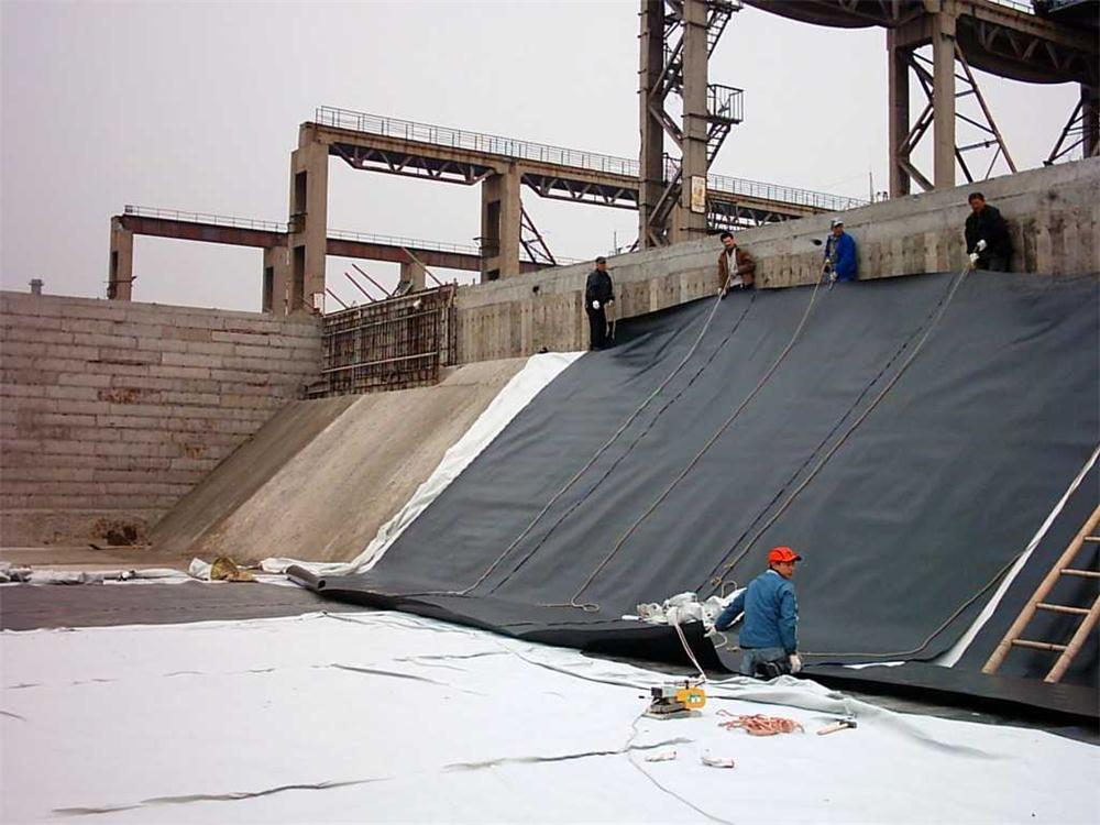
Precise control over extrusion and drawing transforms a material's internal structure in ways that directly shape tensile strength. During extrusion, the melt or billet experiences shear and elongation as it passes through the die, aligning polymer chains or metal grains along the principal stress direction. This preferred orientation, if preserved through controlled cooling, reduces the number of randomly oriented weak boundaries that typically initiate failure under load. Subsequent drawing applies additional plastic deformation beyond the die exit, further refining the microstructure. The degree of cold work, combined with the die angle and reduction ratio, determines how much strength is gained through strain hardening and chain extension.
Fine-tuning these processes means treating tensile strength not as a fixed property but as a dial that responds to processing variables. A smaller die land length with a higher draw ratio can sharply increase yield stress, yet pushing either parameter too far may induce surface cracks or excessive internal stress. Temperature control is equally decisive: drawing below the recrystallization threshold locks in dislocation density for metals, whereas maintaining a controlled temperature window for polymers allows amorphous regions to orient without degrading crystalline zones. Even subtle shifts in haul-off speed or the number of successive drawing passes can shift the strength-ductility balance by several percent, making the difference between a brittle filament and a resilient fiber.
Precision Punching and Aperture Design for Optimal Soil Interlock
The effectiveness of any cellular confinement system hinges on the precision of its perforations. Rather than treating punching as a secondary step, advanced manufacturing processes align each aperture with the specific load path and infill type. This attention to hole geometry, spacing, and edge finish creates a mechanical bond that prevents soil from shifting under repeated traffic or hydraulic pressure. A well-executed punch pattern does more than allow water to drain; it actively distributes stress across the cell wall, reducing localized deformation and preserving the panel's structural integrity over time.
Aperture design plays an equally decisive role in soil interlock. The size, shape, and orientation of each opening determine how readily aggregate or vegetated soil can key into the cell wall. Round or slotted holes each behave differently: round apertures offer uniform stress distribution, while slotted designs improve flexibility for installation on uneven terrain. The spacing between apertures must be tight enough to maintain wall strength but generous enough to prevent clogging and promote root penetration. By fine-tuning these parameters, the system achieves a dense, interlocked matrix that resists lateral movement and surface rutting.
In practice, optimal soil interlock emerges from a balance between openness and containment. Too few apertures trap water and weaken the infill, while oversized or poorly placed holes can compromise the wall and allow fines to escape. Manufacturers that invest in precision punching and iterative aperture testing produce geocells that hold their shape under extreme loads, whether used for slope stabilization, load support, or channel protection. The result is a quieter, more predictable performance that field engineers can rely on without constant adjustment or overbuilding.
In-Line Quality Monitoring: Catching Weak Points Before They Reach the Field
Line-side inspection often gets reduced to a final checkpoint, but that approach lets defects travel too far down the process. Instead, embedding short, focused checks at each critical stage changes the conversation from “what slipped through” to “what did we stop before it could become a problem.” For example, a torque verification right after fastener installation catches a loose joint before panels and trim hide it from view. This isn’t about adding more paperwork; it’s about positioning measurement where the failure is cheapest to correct.
The real value shows up in the data pattern. A single failed check might be an anomaly, but three shifts of slight drift in a crimp height tells you something about tool wear or material batch variation. When operators can see that trend on a simple board next to the line, they start adjusting before the process produces scrap. It’s less about blaming individuals and more about giving the line itself a memory. That feedback loop, even if informal, often outperforms a sophisticated offline audit that arrives days later.
None of this requires a major investment. A go/no-go gauge, a marked reference sample, or a ten-second continuity test can catch most recurring weak points. The trick is consistency: same station, same sequence, same person each time. Once that rhythm takes hold, field returns drop not because the product changed, but because the line stopped shipping its own mistakes. That’s the difference between inspecting quality in and building it without the rework tax.
Adapting Production Parameters for Challenging Ground Conditions
Tunneling through fault zones or water-bearing strata rarely rewards rigid adherence to the original design specs. Operators who treat cutterhead torque and advance rate as fixed values often learn this the hard way—with broken tools, clogged chambers, or sudden face collapses. The practical approach is to treat the machine as a sensing instrument. When torque spikes in mixed-face conditions, reducing RPM while holding thrust steady can keep the excavation cycle stable; conversely, in soft clay, raising rotation speed and backing off penetration prevents the head from becoming a giant blender that liquefies the face.
Ground conditioning additives play a bigger role than most manuals admit. Foam injection ratios, polymer dosing, and the timing of bentonite slurry all need tuning based on real-time observations of spoil consistency and conveyor belt loading. A useful field technique is to collect a spoil sample every ten rings and compare its slump and stickiness against a simple reference chart. If the muck starts balling up on the belt, reduce foam and increase water pressure at the nozzles; if the chamber pressure fluctuates erratically, it may be time to adjust the screw conveyor gate opening rather than fight the ground with brute force.
Finally, record everything that works and everything that doesn't. Challenging ground rarely announces itself with a single warning sign. A sudden drop in torque while thrust remains constant might indicate a void ahead or a transition into weathered rock. By keeping a running log of parameter changes alongside geological observations, tunneling crews build a local playbook that no generic manual can match. That on-the-fly adjustment—backed by careful measurement and honest debriefing—often makes the difference between a project that limps through and one that moves steadily despite the ground's worst intentions.
Testing Beyond the Datasheet: Simulating Real-World Load Scenarios
Most component datasheets present performance under clean, static conditions—fixed resistive loads, constant ambient temperature, and no input voltage ripple. But in actual hardware, a power supply might face a motor that draws inrush current several times its steady-state value, or a digital load that toggles between near-zero and maximum current within microseconds. Testing only against the datasheet numbers leaves a blind spot where real failures tend to hide. The only way to catch these is to reproduce the messy, dynamic behavior of the end application, not the tidy graph on page three.
Simulating real-world load scenarios means more than switching from a fixed resistor to an electronic load. It involves programming current steps with defined slew rates, adding distributed line inductance and capacitance to mimic wiring harnesses, and overlaying AC perturbations on top of the DC load to represent effects like motor commutation noise or processor activity bursts. Some teams even record current waveforms from a working prototype and play them back through a high-bandwidth load to test a new board revision. That kind of test can expose voltage overshoots, control loop instability, or thermal stress that a steady-state soak would never trigger.
The payoff shows up in reliability and field returns. A converter that passes every datasheet test can still shut down intermittently when a nearby relay coil releases, or drift out of regulation when load current changes faster than its error amplifier can respond. By building test setups that reflect how the product will actually be used—including worst-case combinations of load step timing, cable length, and ambient temperature—engineers find the weak points before customers do. It takes more effort up front, but it turns the datasheet from a guarantee into a starting point rather than the final word.
FAQ
Uniaxial geogrids are stretched in one primary direction during manufacturing, aligning polymer chains to deliver high tensile strength along that axis. Biaxial geogrids undergo stretching in two directions, trading some longitudinal strength for balanced transverse performance. For uniaxial products, the extrusion, punching, and controlled drawing stages are tuned to maximize load capacity in the machine direction, which is why they excel in retaining walls and steep slopes.
High-density polyethylene (HDPE) and polypropylene (PP) dominate. HDPE offers excellent resistance to installation damage, chemical attack, and long-term creep under sustained load. PP can provide higher stiffness at lower weight. Some advanced lines blend or co-extrude polymers to balance stiffness, durability, and weldability, but HDPE remains the benchmark for aggressive soil environments.
The punched aperture geometry and spacing determine the rib and junction dimensions before drawing. A well-designed pattern ensures uniform stretching, minimizes stress concentrations, and creates consistent aperture sizes for soil interlock. Advanced factories use CNC-controlled punching and vision inspection to maintain aperture tolerance, which directly affects pullout resistance and load transfer between soil and grid.
Controlled drawing heats the punched sheet to a specific temperature and stretches it at a precise ratio, often between 4:1 and 10:1. This orients the polymer molecules along the drawing axis, dramatically increasing tensile strength and modulus while reducing elongation. The process must be tightly managed; uneven temperature or speed creates weak spots, warping, or premature creep failure.
They use multi-zone ovens, closed-loop tension feedback, and laser or camera-based measurement of rib width and thickness after drawing. Junction integrity is tested by peel and shear tests on samples from every production lot. Automated data logging tracks temperature, draw ratio, and line speed, allowing traceability down to the raw resin batch.
Key tests include tensile strength at 2% and 5% strain, ultimate tensile strength, creep-limited strength, junction efficiency, aperture stability, and resistance to chemical degradation. Long-term design strength is derived from creep rupture testing under accelerated conditions. Advanced producers also perform installation damage trials with site-specific backfill to confirm that survivability meets design assumptions.
Uniaxial geogrids rely on soil particles striking through the apertures, creating a mechanical interlock that transfers load far more effectively than simple friction along a smooth plane. This interlock mobilizes a wider zone of reinforced soil, increasing pullout capacity and reducing the geogrid length needed for stability. Production tolerances in aperture size and rib thickness directly influence this mechanism.
They are primarily designed for high-load directional applications like mechanically stabilized earth walls, steepened slopes, and embankments over soft ground. In soft soil stabilization, they can bridge weak zones when placed in one or two layers, but biaxial or multi-axial geogrids are often more suitable for general subgrade restraint. The choice depends on the dominant stress direction and the required long-term tensile stiffness.
Conclusion
Achieving dependable uniaxial geogrid performance starts long before the first roll leaves the factory floor. The polymer formulation itself is a critical starting point—blending high-density polyethylene or polypropylene with carefully chosen additives, stabilisers, and carbon black to resist UV degradation, chemical attack, and installation damage. Once the right mix is locked in, controlled extrusion and multi-stage drawing become the heart of strength development. By precisely regulating temperature, line speed, and draw ratio, the molecular chains orient along the roll direction, converting modest raw material into a grid with remarkably high tensile stiffness. But strength alone is not enough. Precision punching and aperture geometry determine how effectively the grid interlocks with soil particles. Rib thickness, node integrity, and aperture shape are tuned so that aggregate strikes through and locks in place, transferring load into the geogrid rather than slipping over it. Every batch is monitored in-line—laser gauges, thermal cameras, and tension sensors catch micro-voids, off-spec aperture dimensions, or inconsistent drawing before those weak points ever reach a job site.
Real ground conditions rarely match a clean laboratory test, so the factory adapts its process based on the intended application. For highly alkaline soils or aggressive groundwater, additive packages and drawing parameters are adjusted to preserve long-term durability. In projects with extreme temperature swings, relaxation behaviour is tested through extended creep trials that go beyond standard datasheet values. Instead of relying solely on index tests, the production team simulates actual load scenarios—using full-scale pullout boxes, cyclic loading rigs, and confined tensile testing to replicate the stresses of embankments, retaining walls, or roadway bases. This feedback loop between field simulations and line adjustments means that each production run is tuned not just to meet a specification, but to survive the specific ground challenges it will face. The result is a uniaxial geogrid that delivers predictable, long-lasting reinforcement without surprises after installation.
Contact Us
Contact Person: Jennifer LEE
Email: [email protected]
Tel/WhatsApp: 8618553418999
Website: https://vip.e-baixing.com/wenfengshitong