

Vision Measuring Machine Manufacturer Drives Innovation in Precision Metrology
2026-10-18
Imagine catching a defect smaller than a human hair before it derails an entire production line. That's the promise of advanced vision measuring machines—and JATEN is turning that promise into everyday reality. As a manufacturer driving innovation in precision metrology, JATEN doesn't just keep up with demanding tolerances; it redefines them. Read on to see how.
Rethinking Illumination for High-Contrast Measurements
Most measurement setups still treat illumination as a commodity—just enough light to make the part visible. That assumption quietly caps contrast. When lighting geometry, spectrum, and timing are treated as design variables rather than afterthoughts, surfaces start to separate from noise.
A shallow-angle darkfield sweep can turn a faint scratch into a bright line on a black background. Narrowband wavelengths can isolate a coating response while suppressing substrate reflections. Polarization can be used to strip away specular haze from curved metal or glass.
Combining these modes in fast sequence and merging the frames often yields a contrast that no single image can match. The real rethink is to stop asking whether there is enough light and start asking what information the light is carrying.
The Case for Multi-Sensor Vision Systems on the Shop Floor
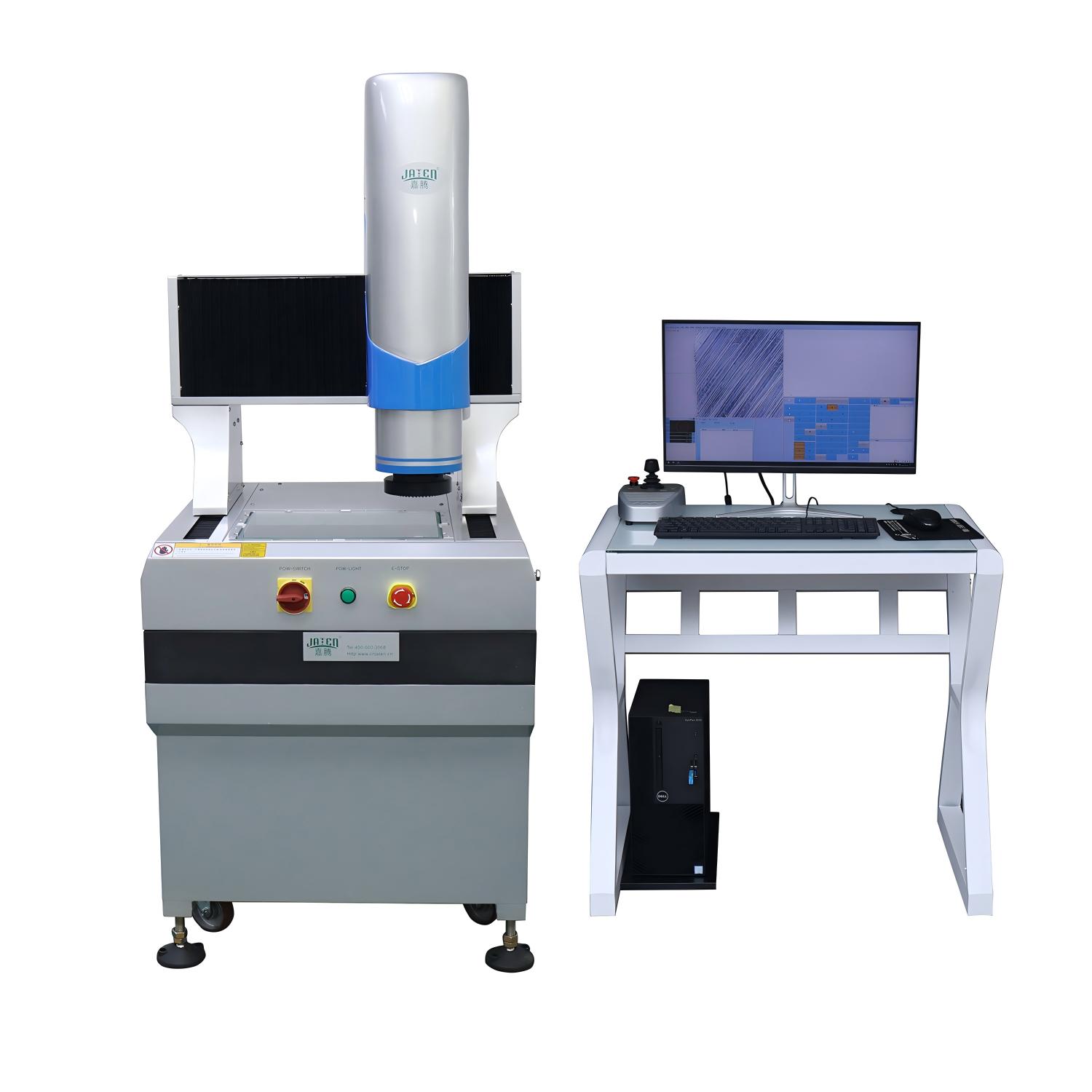
Single-camera inspection setups often miss defects that require more than one perspective or wavelength. Multi-sensor vision systems combine 2D and 3D imaging, thermal, or hyperspectral data to catch flaws invisible to a single modality. On a busy shop floor, this means fewer false passes and less rework downstream.
Beyond accuracy, these systems simplify integration. Instead of synchronizing multiple standalone cameras, a multi-sensor unit can fuse data at the edge, reducing latency and cabling. Maintenance teams also benefit from a single calibration target and one software interface, which lowers the skill barrier for line operators.
The real payoff shows up in high-mix production. When part geometry or surface finish changes, a multi-sensor setup can adapt by re-weighting sensor inputs rather than requiring a full hardware swap. This flexibility keeps inspection lines running through product changeovers without sacrificing throughput.
How Sub-Pixel Algorithms Quiet Noise in Precision Metrology
In precision metrology, the difference between a reliable measurement and a compromised one often comes down to a fraction of a pixel. Raw sensor data carries inherent noise—thermal fluctuations, electrical interference, photon scatter—that smears the true signal across multiple detector elements. Sub-pixel algorithms step into this muddy scene not by chasing perfect hardware, but by modeling where the signal should have landed with decimal-level accuracy. They treat each pixel not as a discrete box, but as a sample of a continuous intensity field, allowing the algorithm to infer a position that falls anywhere within the pixel grid.
The real trick is how these algorithms separate meaningful structure from random jitter. Instead of averaging blindly, they fit a local intensity profile—often a Gaussian or a centroid-weighted model—to the observed pixel values. The peak of that fitted curve becomes the refined location, often resolved to 1/10th or even 1/100th of a pixel. That refinement acts like a filter: low-frequency drift gets tracked, high-frequency noise gets rejected, and the final position estimate carries less uncertainty than any single pixel sample ever could. This matters enormously in applications like wafer alignment, interferometer fringe tracking, or telescope guiding, where a single noisy readout could otherwise misplace a measurement by several micrometers.
What keeps the approach honest is its reliance on statistical repeatability rather than smoothing artifacts. A well-tuned sub-pixel routine preserves sharp edges and fine phase information while reducing the noise floor by squaring the signal-to-noise ratio over multiple frames. The output is not a blurrier image, but a quieter one—where the same physical edge lands at the same decimal coordinate time after time. That consistency is what precision systems actually need: not fewer photons or better cooling, but an interpretation layer that reads between the pixels and refuses to mistake noise for motion.
Calibration Without Guesswork Through Built-In Verification Routines
Precision hinges on eliminating ambiguity. Instead of relying on external reference points or operator intuition, the system embeds automated verification loops directly into its core workflow. Each measurement cycle triggers a sequence of self-checks that compare real-time signal behavior against known physical signatures. If even one threshold drifts beyond tolerance, the routine halts and flags the anomaly before data ever reaches the output stage. This closes the gap between assumption and certainty.
The beauty of built-in routines is their independence from user skill. A novice and a veteran get identical confidence levels because the verification happens silently, without guesswork. Factors like environmental noise, component aging, or minor misalignments are caught by redundant cross-checks that run in parallel. The result is a calibration process that doesn't ask you to trust it—it proves itself on every pass.
Over time, this approach transforms maintenance from a periodic chore into a continuous state of readiness. Rather than scheduling manual recalibrations based on calendars or hunches, the system only signals intervention when internal diagnostics indicate a genuine need. That means fewer false alarms, less downtime, and a traceable audit trail that documents exactly how each verification was performed. Guesswork becomes a relic of older, external-calibration thinking.
Turning Point Clouds into Practical Pass/Fail Decisions
Point cloud data alone rarely answers the only question a production line cares about: does this part pass or fail? The shift starts by mapping scanned points to the nominal CAD model, then computing signed distances for every measured location. Those distances are not just a heat map; they become the raw material for a clear rule set. A bore that drifts more than 0.15 mm from its designed center, a flange face that tilts beyond 0.2 degrees, or a surface whose maximum deviation exceeds the profile tolerance all trigger a reject. Setting these thresholds upstream, in the same coordinate system as the design intent, removes guesswork from the operator and turns a dense scan into a binary choice.
The practical value appears when pass/fail logic is tied to the features that actually matter, not to every point equally. Instead of a global RMS error that hides a critical local defect, inspection routines can isolate zones: mounting holes, sealing surfaces, snap-fit edges. For each zone, define a tolerance band and a coverage requirement, such as at least 95% of scanned points within that band. If the tail of the distribution crosses the band, the part fails even if the average is fine. This zonal approach mirrors how engineers already think about drawings and avoids the trap of over-rejecting good parts due to noise in irrelevant areas.
Finally, the decision needs to be stable and repeatable. Point clouds from different scanners or slight fixture shifts can alter raw coordinates, but the pass/fail outcome should not flip for a part that is borderline only because of registration error. Anchoring the comparison to robust datum features, using a fixed voxel size for downsampling, and storing the distance-to-tolerance ratio for each zone make the call defensible. Over time, those ratios also reveal which features drift toward the limit before a hard fail occurs, giving process engineers a lead indicator rather than just a scrap count.
Vision Metrology Outperforms Traditional Contact Methods in Tight Tolerances
When tolerances drop to a few microns, even a light touch introduces uncertainty. Traditional CMMs rely on a physical stylus that must physically contact the surface, which can distort thin-walled parts, compress soft materials, or leave microscopic scratches on polished finishes. Vision metrology sidesteps all of this by capturing data with cameras and structured light, so the part remains untouched. The absence of contact force means measurements reflect the true geometry rather than the geometry under load. For delicate components like fuel injector nozzles or medical micro-molds, that difference is often the line between pass and fail.
Another overlooked advantage is how vision systems handle dense feature arrays. A tactile probe must travel point to point, stopping at each hole, slot, or edge, which drags out cycle times and accumulates positioning error. Vision metrology grabs the entire field of view in a single snapshot, then extracts dozens or hundreds of features simultaneously. This not only speeds up inspection but also removes the drift that creeps into long CMM programs. With sub-pixel edge detection, modern cameras can resolve edges to within a fraction of a pixel, delivering repeatability that rivals or beats contact methods on features smaller than the stylus tip itself.
There is also the matter of access. Contact probes need a clear path to reach each measured surface, which often requires multiple setups or complex rotary tables. Vision systems can inspect recessed areas, sharp internal corners, or features behind transparent windows that a stylus could never touch. In tight-tolerance production, reducing setups means fewer opportunities for datum mismatch, and the ability to measure what you cannot physically reach is invaluable. For any manufacturer chasing single-digit micron tolerances, the question is not whether vision can match contact methods, but why anyone would still use a stylus for dimensions it cannot safely touch.
FAQ
They've focused on blending high-resolution optics with real-time software correction, which lets their systems hold sub-micron repeatability even in less-than-ideal shop conditions. That practical robustness, not just lab specs, is what manufacturers notice.
Their development cycle is tied closely to customer tolerance failures. When a client reports a bottleneck or a measurement uncertainty issue, that feedback directs the next sensor or lighting upgrade. It's incremental but grounded in actual production pain.
Aerospace, medical device, and micro-electronics teams see the biggest gains because they need to verify complex geometries and tiny features without slowing down the line. One medical maker cut inspection time by 40% after switching from manual optical comparators.
The software is the differentiator. It handles edge detection under variable lighting, auto-generates measurement routines from CAD files, and offers offline programming so a new part can be set up without tying up the machine.
Yes, through a combination of optical imaging, laser scanning, and touch probing in some configurations. Operators can switch between fast 2D profiles and full 3D surface maps in the same program, which removes the need for separate CMM inspections.
They emphasize on-site training and shadow-graph-to-vision migration help. Instead of handing over a manual, their engineers will run a pilot batch with the customer's own parts and build the first measurement programs together, so the team gains confidence quickly.
It shows up as things like sub-two-micron volumetric accuracy on a benchtop unit, or a lighting system that adapts to surface finish automatically. These aren't headline features—they're daily workhorses that reduce scrap and rework.
Speed and non-contact safety are the main reasons. A vision system can capture hundreds of points in seconds without marking delicate surfaces, and it can inspect features too small or too flexible for a touch probe. For high-mix production, that flexibility is hard to beat.
Conclusion
Precision metrology has long struggled with noisy edges and unreliable lighting. One vision measuring machine manufacturer is attacking those weaknesses at the source. By redesigning illumination paths for high-contrast surface capture, their systems reveal subtle geometry that conventional ring lights wash out. On the measurement side, sub-pixel algorithms suppress noise without blurring true edges, so repeatability improves even under fluctuating shop-floor conditions. Calibration used to demand external reference artifacts and periodic manual checks. This manufacturer embeds verification routines directly into the machine, letting operators confirm accuracy in seconds rather than hours. The result is a measurement process that trusts its own numbers, not just a certificate on the wall.
Beyond a single camera, these platforms combine optical, laser, and tactile sensors to handle parts that would frustrate a pure vision system. Instead of dumping raw point clouds onto an engineer's desk, the software turns that data into pass/fail decisions that a machinist can act on immediately. The shop-floor impact becomes obvious in tight-tolerance work where traditional contact probing either deforms delicate surfaces or cycles too slowly. Here, non-contact vision measurements handle hundreds of features per minute while holding micron-level uncertainty. That speed and rigor let manufacturers move inspection from a lab bottleneck to the production line, catching drift before it becomes scrap. In a field where a few microns decide profitability, this approach redefines what in-process metrology can deliver.
Contact Us
Contact Person: Volien
Email: [email protected]
Tel/WhatsApp: +86 18029161762
Website: https://www.jatentech.com/